

Introduction:-
Australia's Queensland State Government in 2006 established a design brief on a pedestrian bridge with low budget hardly possible in state capital, Brisbane to establish link with Queensland Gallery of Modern Art (GoMA). Baulderstone(contractor), Arup(engineer) and Cox Rayner(architect) won the design competition with a design, fusion of art and science having array of masts, cables and flying steel spars well suited with locality, structurally efficient and completely original. More on “tensegrity”.
Australia's Queensland State Government in 2006 established a design brief on a pedestrian bridge with low budget hardly possible in state capital, Brisbane to establish link with Queensland Gallery of Modern Art (GoMA). Baulderstone(contractor), Arup(engineer) and Cox Rayner(architect) won the design competition with a design, fusion of art and science having array of masts, cables and flying steel spars well suited with locality, structurally efficient and completely original. More on “tensegrity”.
Key statistics
Ø Bridge deck 430m long x 6.5m clear width
between handrails
Ø 500m3 of concrete and 500
tonnes of steel
Ø
Nearly
7km of high strength steel cables


All the possible solution in front of the team and why
there were discarded is shown below:-
OPTION
|
HINDERANCE
|
DECISION
|
Cable-stayed
|
Large mast Visually Dominant
|
No
|
Arch
|
Poor soil condition
|
No
|
Suspension
|
Poor soil condition
|
No
|
Tube
|
Promising but difficult to
construct
|
No
|
Tensegrity mast-and-cable
|
Satisfies all aspect
|
Yes
|
Superstructure form and details
Ø
3 main sections separated from central by expansion joint
and bearings:-
1.
Point approach(120m)
2.
Tensegrity itself(3 spans of 58m, 128m and 45m)
3.
Tank street approach(82m)
Ø
Mainly used composite steel (masts, cables, ties,
tensegrity canopy) and concrete for deck structure.
Ø Tensegrity bridge elements:-
1.
Masts:- fabricated tubular steel sections up to 30m long
with section 610-905mm diameter.
2.
Major mast cables:- high-strength spiral wound galvanized
wire ropes 30-80mm diameter.
Ø
Precast deck panels were used which were stitched by in
situ concreting.
Ø Edge Beams separated from deck has fabricated box sections having curved
outer face for aerodynamic stability.
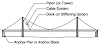
Ø Pairs of major raking tubular steel masts spring from the main support
piers on either sides of the main span, setting the locations of an
approximately coplanar array of minor secondary masts. The major and minor
masts are offsets from the perpendicular both longitudinally and transversely,
thus preventing cable/mast or cable/cable clashes and providing the signature “Randomness”
without much reducing structural efficiency. Secondary cables connected to
flying struts, themselves pure tensegrity elements (only supported by cables),
provide lateral restraint to the masts.
Ø The tensegrity array of
flying struts and cables that hovers above and beside the deck fulfils three
critical functions:
1.
It laterally restrains the tops of all the masts,
preventing them from buckling sideways under the loads arising from the
suspension of the deck plus lateral and seismic forces.
2.
It suspends the canopy, allowing it to float above the
deck with no apparent means of support.
3.
It laterally restrains the tops of all the masts,
preventing them from buckling sideways under the loads arising from suspension
of the deck plus lateral and seismic forces.
4.
It works in unison with all the masts and cables to
resist twisting and lateral forces arising from patch loads on the deck (i.e.
crowds), wind and earthquakes.


0 Comments